
TN 5.04_C HDPE and HP Storm Connections to Manholes and Structures
Filename:
TN 5.04_C HDPE and HP Storm Connections to Manholes and Structures.pdf
This document is the TN 5.04_C HDPE and HP Storm Connections to Manholes and Structures. Overview, connections and installation provided with figures and descriptors.
A full line of pipe jointing options is available to fit the requirements of nearly any storm drain or gravity flow project specifications. The joints available range from soil tight split couplers to gasketed soil-tight (ST) and watertight (WT) pipe. When connecting pipe to drainage structures it is important to make those connections with a joint performance at least equal to that of the piping system.
When using soil-tight pipe in non-watertight applications, it may be acceptable to grout the void space between the pipe and drainage structure. When using watertight pipe for testable systems, requiring some degree of watertight performance, it is necessary to provide additional measures to insure a watertight connection between the pipe and structure. ASTM F2510/F 2510M, “Standard Specification for Resilient Connectors Between Reinforced Concrete Manhole Structures and Corrugated High Density Polyethylene Drainage Pipes,” is the governing standard for corrugated HDPE pipe-manhole connections, but specific performance/installation requirements should be verified for each specific project. Along with a full line of adapter fittings available, including the Waterstop® Gasket, are flexible boot fittings provided by other manufactures. Fitting dimensions should be supplied to the manufacturer to insure the proper fitting size and manhole boot connector are supplied.
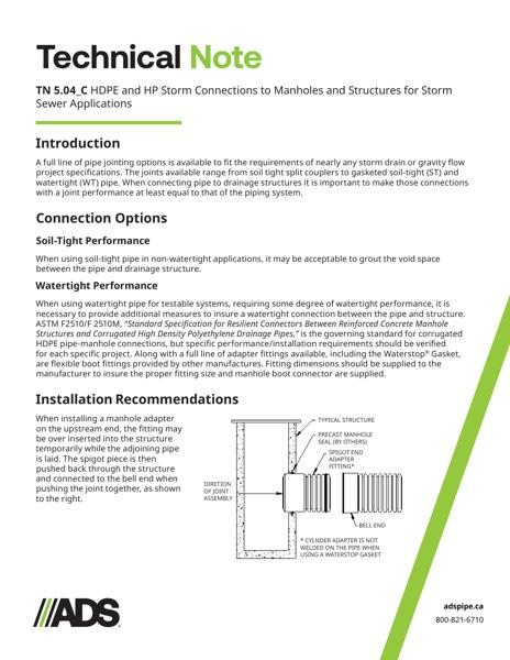
When installing a manhole adapter on the upstream end, the fitting may be over inserted into the structure temporarily while the adjoining pipe is laid. The spigot piece is then pushed back through the structure and connected to the bell end when pushing the joint together, as shown to the right. A figure shows the components.
Alternately, when using the adapter fitting in the downstream end of the structure, before pushing the bell and spigot together from inside the structure, it is necessary to provide blocking at the structure to prevent the fitting from moving in the structure, as shown to the left. A figure shows the components.